GHFM-01 Guarded Heat Flow Meter is designed to test the thermal resistance and thermal conductivity of both homogeneous and heterogeneous materials.
We are happy to arrange a live demonstration for you!
Please enter your email to download the brochure.
The Guarded Heat Flow Meter (GHFM-01) follows ASTM E1530-19 for testing thermal resistance and thermal conductivity of solids, such as metals, polymers, composites and paste from -20 °C to 310 °C. The Thermtest proprietary testing stack, replaces the traditional pneumatic movement with advanced motor control, which allows automated control of testing sample thickness, force or pressure applied.
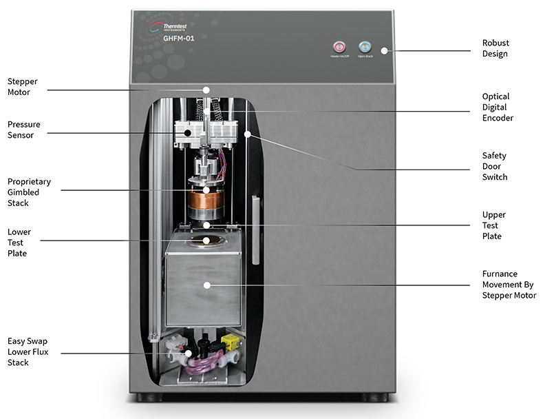
The advanced GHFM-01 is a primary measurement of thermal resistance—thermal conductivity for solids, such as metals, polymers, composites and paste. Specifically, the calculation of thermal conductivity from measurement of thermal resistance is the most accurate method of testing the true thermal conductivity of heterogeneous materials. The steady-state measurement of thermal resistance represents the full sample thickness and mature heat transfer properties.
According to the method, the sample is subjected to a steady-state through-thickness temperature gradient. The thermal conductivity of the sample is obtained by measuring the temperature difference across it, and one additional temperature.
The testing stack is made up of a heater – upper plate, with integrated temperature sensor and heat sink—lower plate with integrated temperature sensor on each side of the sample. Additional temperature sensors are placed near the top and bottom surface of the sample.
Once steady-state temperature across the sample is achieved, the Fourier law equation can be applied. The ratio RS (m²•K/W), equal to the thickness of the sample, d (m) to its thermal conductivity, λ (W/m•K), can be obtained from the temperatures measured:

Materials | Metals, polymers, composites, and pastes |
|---|---|
Type of Sensors | Thermocouples (x6) |
Direction | Through-thickness |
Thermal conductivity (W/m·K)* | 0.1 to 100 |
Sample diameter (mm) | 50 to 50.8 |
Sample thickness (mm) | Up to 25 | Thin-films down to 0.1 mm with optional software |
Test time (minutes) | 40 to 60 |
Accuracy (Thermal conductivity) | 3% |
Repeatability (Thermal conductivity) | 1 to 2% |
Temperature range (°C)** | -20 to 310 |
Pressure (kPa | psi) | Automated up to 379 kPa (55 psi) |
Standard | ASTM E1530-19 |
*Above 60 W/m·K, the material should be a minimum of 12.5 mm thick
**Chilled circulator included with each system
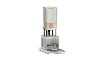
No tools are required to change the lower Heat Flux Stack, which forms a calibrated Heat Flux Transducer.
Housing multiple thermocouples to monitor temperature for confirmation of steady-state condition of the temperature gradient across the sample is achieved
Our proprietary gimbal design has the advantage of either automatic determination of sample thickness for rigid materials or a user defined sample thickness for compressible materials.
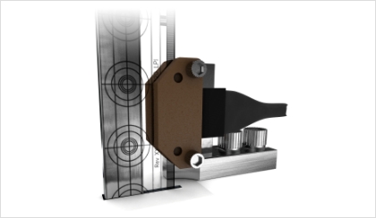
Sample thickness is measured using digital optical encoder technology.
Optimally selected heaters cooled by heat exchangers matched with thermocouples are positioned in the upper and lower stack to accurately control plate temperatures.
Lateral heat loss is minimized with the use of a guard oven. Upper and lower plates along with guard oven temperatures are controlled by the convenient software.
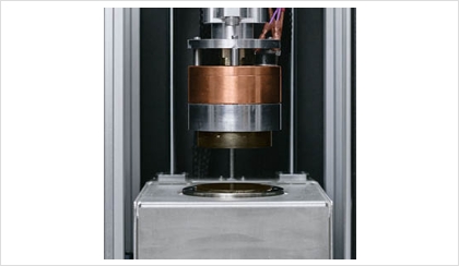
Plates automatically clamp together for optimum sample contact for rigid materials. When testing compressible materials, the desired height, force, or pressure is set in the software and the plate will automatically stop once desired sample height, or pressure is achieved.
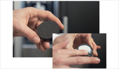
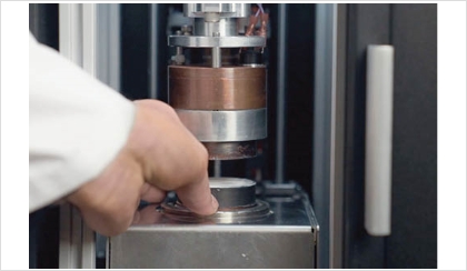
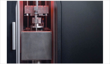
Using the GHFM-01 Software, the user is able to schedule unlimited temperature steps up to 300 °C. Internal red backlight signals testing in progress.
Approximate Time: 40 to 60 mins.
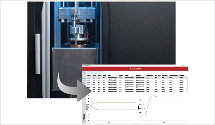
Approximate Time: 1 min.
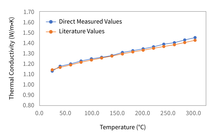
Demonstrating the performance of the GHFM-01, measurements on Pyrex 7740 were made up to 300 °C and compared to literature values.
Temperature ( °C) | 25 | 40 | 60 | 80 | 100 | 120 | 140 | 160 | 180 | 200 | 220 | 240 | 260 | 280 | 300 |
|---|---|---|---|---|---|---|---|---|---|---|---|---|---|---|---|
Direct Measured Values | 1.134 | 1.172 | 1.192 | 1.223 | 1.246 | 1.261 | 1.280 | 1.307 | 1.325 | 1.343 | 1.361 | 1.386 | 1.401 | 1.426 | 1.451 |
Literature Values | 1.143 | 1.164 | 1.214 | 1.236 | 1.236 | 1.257 | 1.276 | 1.295 | 1.313 | 1.330 | 1.348 | 1.366 | 1.385 | 1.404 | 1.426 |
Error (%) | 0.80 | 0.71 | 0.11 | 0.71 | 0.75 | 0.33 | 0.27 | 0.96 | 0.92 | 0.99 | 0.98 | 1.44 | 1.19 | 1.54 | 1.78 |
Models | |
Materials | Metals, Polymers, Composites, and Pastes |
Measurement Capabilities | Through-Thickness |
Applications | General Testing |
Thermal Conductivity Range | 0.1 to 100 W/m•K * |
Sample Diameter | 50 to 50.8 mm |
Sample Thickness | Up to 25 mm | Thin-films down to 0.01 mm with optional Software |
Maximum Thickness | 25.4 mm / 1 in. |
Temperature Range | -20 to 310 °C ** |
Pressure | Automated up to 379 kPa (55 psi) |
Measurement Time | 30 to 45 minutes |
Accuracy | ± 3 % |
Repeatability | ± 1 to 2 % |
Standards | ASTM E1530-19 |
Simply fill in the form and submit. One of our qualified team members will reach out to you to offer a price that fits your needs.
