Heat flow meter for measuring the thermal conductivity and thermal resistance of insulation and construction materials.
We are happy to arrange a live demonstration for you!
Please enter your email to download the brochure.
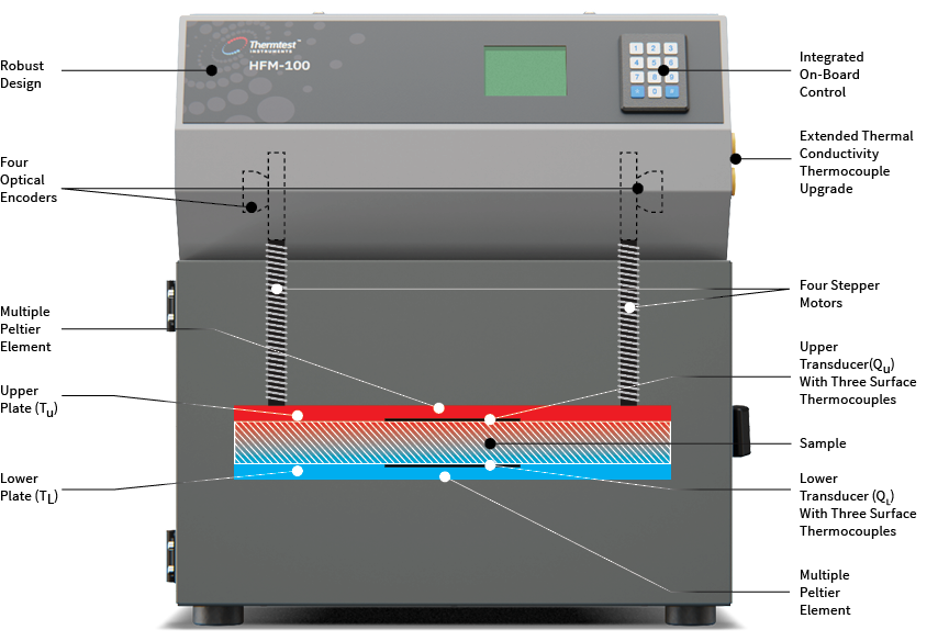
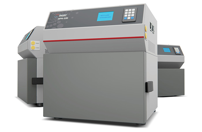
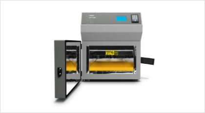
The second generation HFM-100 / HFM-100 HT / HFM-50 instruments are an excellent choice when making steady-state thermal conductivity measurements of specimens like insulation products and construction materials. We’ve rigorously engineered the Heat Flow Meter (HFM) to meet the requirements of international standards including ASTM C518, ASTM C1784, ISO 8301, JIS A1412, EN 12667 and EN 12664. Operating the HFM is straightforward—a sample is positioned between two heating and cooling plates. The upper plate, powered by stepper motors positioned in each corner, lowers to contact the top of the sample. Plate contact with the test specimen is controlled by a standard applied pressure, or by a user defined specimen thickness.
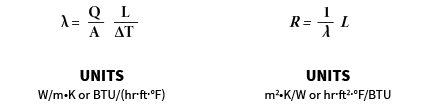
Stepper motors are controlled by individual optical encoders for the measurement of sample thickness (L), to the nearest 0.05 mm (0.0019 in). Integrated logic between stepper motors allows the upper plate to sense and adjust for specimens with surface variations, optimizing plate – specimen contact for measurements. One heat flux sensor is integrated into each plate, and is used to monitor heat flux (Q/A), generated due to the difference in temperature (ΔT) between the top and bottom plate at regular intervals, until steady-state heat flux is observed. The composite heat flux is then used to measure thermal resistance (R) and calculate thermal conductivity (λ) according to Fourier’s Law.
Following international standards, the HFM Series is designed for testing both homogeneous and heterogeneous materials of a range ofsample dimensions.
Methods | HFM-100 | HFM-100 HT | HFM-50 | HFM-25 |
|---|---|---|---|---|
Materials | Insulation, solids, and textiles | Insulation, solids, and textiles | Insulation, solids, and textiles | Insulation, solids, and textiles |
Type of Sensors | Flux sensors (x2) | Flux Sensors (x2) | Flux sensors (x2) | Flux sensors (x2) |
Thermal conductivity (W/m•K) | 0.002 to 0.5 | 0.002 to 0.5 | 0.002 to 0.5 | 0.01 to 0.3 |
Specific heat | Optional | Optional | Optional | N/A |
High thermal conductivity kit (W/m•K) | Optional (up to 2.5) | Optional (up to 2.5) | Optional (up to 2.5) | N/A |
Sample size (mm) | 300 x 300 x up to 100 | 300 x 300 x up to 100 | 200 x 200 x up to 50 | Up to 300 x 300 x 25 |
Test time (minutes) | 30 to 40 | 30 to 40 | 30 to 40 | 20 |
Accuracy (Thermal conductivity) * | 1 to 2% | 1 to 2% | 1 to 2% | 3% |
Repeatability (Thermal conductivity) | 0.5 to 1% | 0.5 to 1% | 0.5 to 1% | 1% |
Plate temperature range (°C) | 20 to 75** | -30 to 110** | -20 to 70** | 10 to 75 |
Factory calibrated | Yes | Yes | Yes | Yes |
Standard | ASTM C518, ASTM C1784, ISO 8301, JIS A1412, EN 12667, and EN 12664 | ASTM C518, ASTM C1784, ISO 8301, JIS A1412, EN 12667, and EN 12664 | ASTM C518, ASTM C1784, ISO 8301, JIS A1412, EN 12667, and EN 12664 | ASTM C518, ISO 8301, JIS A1412, and EN 12667 |
*Performance verified with NIST 1453 / 1450e
**Chilled circulator required
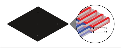
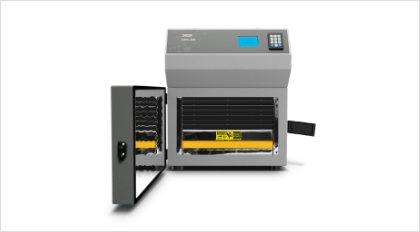
A heat flux sensor is a thermopile sensor, consisting of thermocouple junctions arranged uniformly across the sensor surface. Each individual junction generates an electrical voltage, proportional to the difference in temperature across the hot and cold junctions of the thermocouple. For accurate measurements of heat flux, one flux sensor with three surface thermocouples is integrated into the surface of each testing plate of the HFM. This intimate contact reduces the level of calibration required, resulting in improved test results.

Thermoelectric Peltier elements are used to heat and cool the HFM testing plates. A thermoelectric element is a solid-state active heat pump which transfers heat from one side of the device to the other, with consumption of electrical energy, depending on the direction of the current. This flexibility allows the user to easily change heating and cooling direction to best match their testing application, at a temperature resolution of <0.01°C (0.018°F). Each plate contains multiple high power thermoelectric modules, matched with a surface thermocouple and smart temperature control to optimize the speed and accuracy of the plate temperatures.
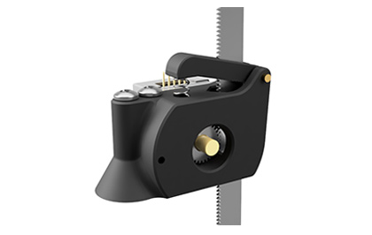
Accurate sample thickness is optimal for determining the thermal resistance of a material with the measurement of thermal conductivity. The HFM-100 system features the advantage of either an automatic determination of sample thickness, for rigid materials, or a user defined sample thickness, for compressible materials. Sample thickness is measured using digital optical encoder technology. Four encoders are positioned at each corner of the top sample plate. Multi-position encoder placement ensures the most accurate (< 0.05 mm / 0.0019 in) measurement of sample thickness, and in the end, thermal resistance for materials being measured. The design of the encoder assembly allows for constant and reliable coupling of the plate and optical encoder via a securely attached gear rack. By keeping the gear rack perfectly coupled to the encoder at all times, the HFM is able to intelligently and precisely resolve any misalignment of the plates.
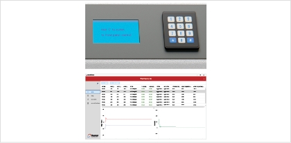
The HFM offers users two versatile and convenient methods of operation—run your measurements independently using the integrated front control panel, or by using the feature packed Windows based HFM software included with each system. The simple to use software offers additional features over the front panel operation, including unlimited steps of temperature automation when testing, and additional functions like saving, exporting, and printing measurement results. With front panel control, users can automate up to five steps of temperature when making measurements, or unlimited steps with the HFM software. HFM results are conveniently available in both SI, and Imperial Units of measure.
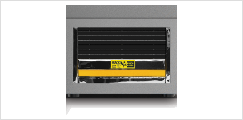
For rigid materials, plates automatically clamp together for optimum contact between sample and heat flux sensors. For compressible materials, the desired height of the sample may be entered manually and the plate will automatically stop at the entered sample height.
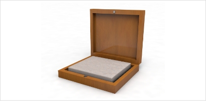
Every HFM system comes complete with one Standard Reference Material (SRM) from the National Institute of Standards and Technology (NIST). SRM 1450e- Fibrous Glass-Board is certified for thermal conductivity from 6.85 to 66.85˚C (44.33 to 152.33˚F) and is available in a thickness of 25 mm (1 in). Additionally available is SRM 1453 – Expanded Polystyrene Board is certified for thermal conductivity from 7.85 to 39.85˚C (46.13 to 103.73˚F) and is available in a thickness of 12.5 mm (0.5 in). In addition to NIST Standard Reference Materials, we can develop Thermal Transfer Standards (TS) for specialized testing applications.
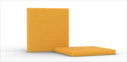
The sample should have parallel surfaces. Sample height is automatically measured by the HFM; however for compressible materials, desired sample thickness can be manually entered for predetermined testing thickness.
Place the sample between the HFM’s parallel testing plates. For smaller samples or samples of differing shapes from the testing chamber, place the sample within the center of the lower plate, positioned directly over the heat flux sensor.
A single mean temperature or steps of temperature may be selected for an automated testing routine. Testing can be performed in either quality control or high accuracy (30 to 40 min.) modes for test times which best fit your application. Once testing is complete, results can be saved, printed, or exported to Microsoft Excel for further processing.
Approximate Time: 30 – 40 min.
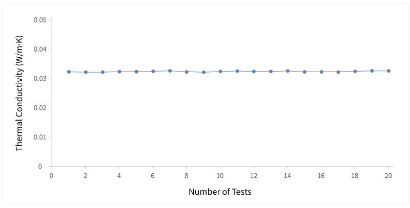
A sample of NIST SRM 1450d was repeatedly tested to confirm the accuracy and repeatability of the HFM-100. Prior to each of the 20 measurements, the NIST 1450d sample was removed, and then placed back within the HFM-100 chamber. The certified thermal conductivity for the NIST piece at 20˚C (68˚F) is 0.03239 W/m•K. The average thermal conductivity value received from all 20 tests was 0.0325 W/m•K. All tests had a repeatability within ± 0.5%, and an accuracy within ± 1% of the certified value.
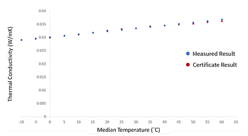
The Thermtest HFM-100 is capable of testing materials over a temperature range of -20 to 75°C (-4 to 167˚F). NIST 1450d, Fibrous Glass Board, is a certified Standard Reference Material from the National Institute of Standards, and Technology. Measured results are within 2% of the certified values.
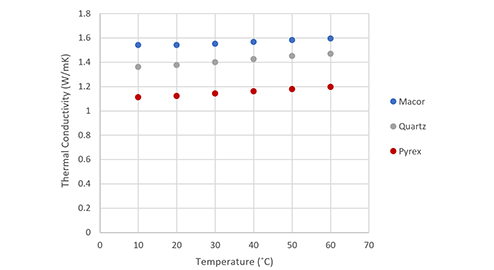
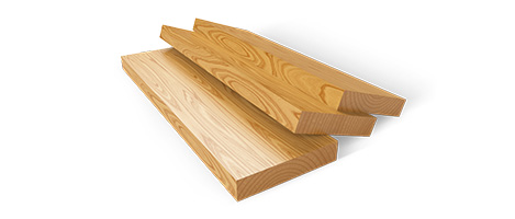
With the added High Thermal Conductivity Kit, the HFM-100 / HFM-50 are able to accurately and efficiently measure higher thermal conductivity materials, such as glass and ceramics. For such applications, an external thermocouple kit is used in combination with the sample being tested. Macor, Quartz, and Pyrex were tested in the HFM from 10˚C to 60˚C (50˚F to 140˚F). All measured values are within the stated accuracy of the system, ± 5%.
When testing compressible materials, such as batting insulation, slight changes to the density of a material, due to compressive forces, may alter thermal conductivity. Both a fiberglass and a stone wool batting insulation were tested with the HFM. A thermal conductivity of 0.0430 W/m•K was the result of the fiberglass testing, where 0.0364 W/m•K was the result of the stone wool insulation test. These values were within 3% of the stated manufacturers thermal conductivity.
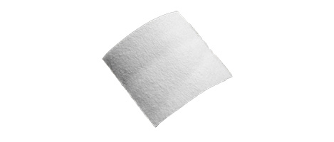
Aerogel has one of the lowest thermal conductivities known to solids. An aerogel blanket of choice was selected to test by the Heat Flow Meter. Results concluded a thermal conductivity of 0.014 W/m•K, which is within 3% to the manufacturers specification.
Simply fill in the form and submit. One of our qualified team members will reach out to you to offer a price that fits your needs.