
| |
|---|---|
Models | |
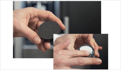
Materials | Metals, Polymers, Composites, and Pastes |
Measurement Capabilities | Through-Thickness |
Applications | General Testing |
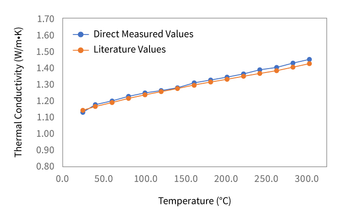
Thermal Conductivity Range | 0.1 to 100 W/m•K * |
Sample Diameter | 50 to 50.8 mm |
Sample Thickness | Up to 25 mm | Thin-films down to 0.01 mm with optional Software |
Maximum Thickness | 25.4 mm / 1 in. |
Temperature Range | -20 to 310 °C ** |
Pressure | Automated up to 379 kPa (55 psi) |
Measurement Time | 30 to 45 minutes |
Accuracy | ± 3 % |
Repeatability | ± 1 to 2 % |
Standards | ASTM E1530-19 |